A good PCB layout and grounding scheme is crucial for optimal performance. Mini-Circuits recommends a 4-layer PCB with a solid ground plane, and to connect the device's ground pins to the ground plane using vias. Additionally, keep the signal traces short and away from noise sources.
To ensure proper biasing, follow the recommended biasing circuit in the datasheet. Use a voltage regulator to provide a stable voltage supply, and add decoupling capacitors to filter out noise. Also, ensure the bias resistors are of high quality and have low thermal noise.
The SCG-2-242+ can handle up to 1W of input power. However, it's recommended to derate the power handling to 0.5W or less to ensure reliable operation and prevent overheating.
To troubleshoot common issues, start by checking the PCB layout and grounding scheme. Ensure that the device is properly biased and that the input and output impedances are matched. Use a spectrum analyzer to identify any unwanted oscillations or spurious signals. If issues persist, consult the datasheet and application notes or contact Mini-Circuits' technical support.
Yes, the SCG-2-242+ can be used in a push-pull configuration to achieve higher output power and improved linearity. However, this requires careful design and layout considerations to ensure proper operation and to prevent oscillations.
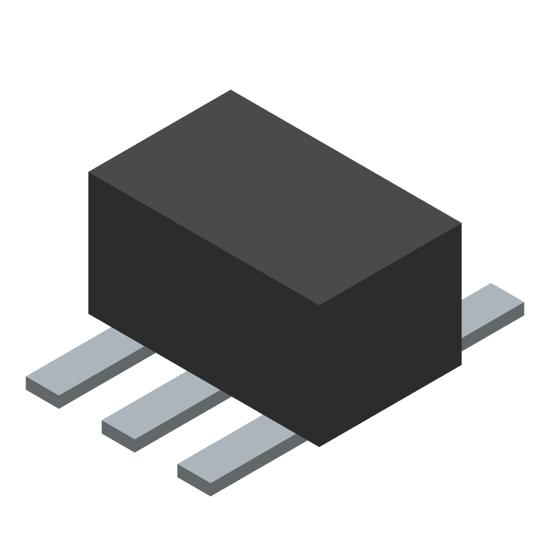 SCG-2-242+ datasheet
by Mini-Circuits
SCG-2-242+ datasheet
by Mini-Circuits