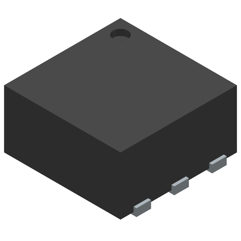
Mini-Circuits provides a recommended PCB layout and footprint in their application notes, which can be found on their website. It's essential to follow these guidelines to ensure optimal performance and minimize parasitic effects.
The MTY2-243+ has a nominal impedance of 50 ohms. To impedance match, use a pi-network or a T-network with resistors and capacitors to match the amplifier's input and output impedance to your system's impedance. You can use online impedance matching tools or consult with an RF engineer for assistance.
The MTY2-243+ is rated for operation from -40°C to +85°C. However, it's recommended to derate the amplifier's power dissipation above 60°C to ensure reliable operation and prevent overheating.
Yes, the MTY2-243+ can be used in a push-pull configuration to improve linearity and reduce distortion. However, this requires careful design and layout to ensure proper phasing and impedance matching.
The MTY2-243+ requires a single positive supply voltage (Vcc) and a negative supply voltage (Vee) for biasing. A recommended biasing scheme is to use a voltage divider network to set the gate voltage, and a current-limiting resistor to set the drain current. Consult the datasheet and application notes for more information.